I bought this diagnostic card from AliExpress but the instructions were not the best but there is a lot of information in the product page. I am merging the information I find here.
- TL631 Pro Universal Laptop And PC PCI PCI E Mini PCI E LPC Motherboard Diagnostic Analyzer Tester Debug Cards|Instrument Parts & Accessories| - AliExpress
- Some examples of how users have used their debug cards
- Eakins Store are good to deal with
Other Notes
- If a motherboard has a PCI slot and PCIE slots. there is a good change the debug headers are in the PCI socket, it will not be in both.
- only one of the PCIE/PCI sockets might support debug. This is useful to know.
Another description
- TL631 PRO uses the new 130-nanometer Actel ProASIC3 flash memory series chip with a new pure system.
- Gemini drive module: BGA type driver module, part design.
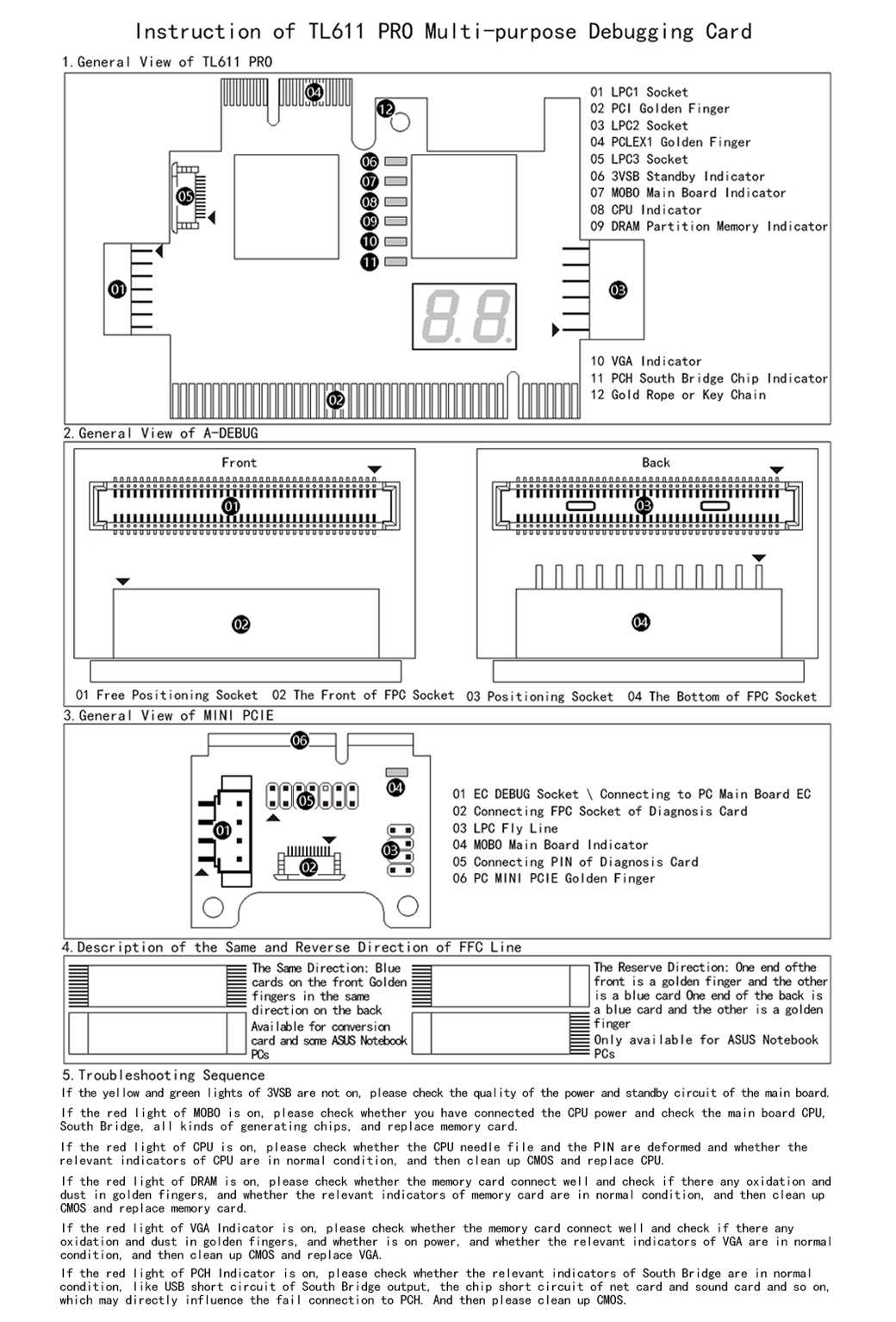
TL631 Pro interface description:
- LPC1 shared high-speed channel = connect to the motherboard 2.0 small pin LPC interface, 2.0 module
(Module expansion LPC3 interface can connect notebook MINI PCIE conversion card, A-DEBUG conversion card, ASUS notebook DEBUG-CON. EC-DEBUG). - PCI high-speed channel = support all PCI slots.
- LPC2 shared high-speed channel = connect to the motherboard 2.54 large pin LPC interface, ASUS COM-DEBUG. ASRock UART1, MSI JDP, SuperMini SPl.
- PCIE X1 high-speed channel = support Gigabyte without PCI motherboard (other brands do not support).
- 3VSB power indicator, to detect whether the power is normal.
- RST reset indicator, to detect whether the motherboard reset is normal (only when PCI or PCIE is inserted)
- CPU indicator light, to detect whether the CPU module is normal.
- DRAM memory indicator, to detect whether the memory module is normal.
- VGA graphics indicator light, to detect whether the graphics card module is normal.
- PCH south bridge indicator light, to detect whether the south bridge module is normal.
- DP decimal point, CLK signal display.
- DP decimal point, FRAME frame signal display.
- threading hole
Package Contents:
1 * TL631 Pro Diagnostic Card
1 * MINI adapter board
1 set * cables
1 * 2.0 modules
2 * 2.54 modules
TL631 Pro interface description:
- LPC1 high-speed shared channel, connect to the motherboard 2.0 small pin header LPC interface, 2.0 module (module expansion LPC3 interface which can be connected to notebook MINI PCIE conversion card, A-DEBUG conversion card, notebook DEBUG-CON, EC-DEBUG)
- PCI high-speed channel, support all PCI slots.
- LPC2 shared high-speed channel, connect to the motherboard 2.54 large pin LPC interface, COM-DEBUG, ASRock UART1, MSI JDP, Supermicro SPl.
- PCIE X1 high-speed channel, support Gigabyte no PCI motherboard (other brands do not support).
- 3VSB power indicator to detect whether the power is normal.
- RST reset indicator to detect whether the motherboard reset is normal (only when PCI or PCIE is inserted)
- CPU indicator light to detect whether the CPU module is normal.
- DRAM memory indicator to detect whether the memory module is normal.
- VGA graphics indicator light to detect whether the graphics card module is normal.
- PCH indicator light to detect whether the southbridge module is normal.
- CLK signal display, FRAME frame signal display.
Specifications:
- Name: Diagnose Card
- Material: printed circuit board
- TTL631 PRO Full Set
- Item size: 78 * 52mm / 3.07 * 2.05in
- Package size: 150 * 100 * 100mm / 5.91 * 3.94 * 3.94in
- Package weight: 170g / 6.00ounce
Packing List (TL631 PRO Full Set):
- 1 * TL631 PRO Diagnose Card
- 1 * MINI PCIE Conversion Card
- 1 * A-DEBUG Conversion Card
- 4 * Wires
Overview
The Full Kit (get this one)

Warnings

Adapters


Supported Headers
The TL631 supports all the headers the TL611 did and the new ones.


Identification of Components

- LPC1 shared high-speed channel = connect to the motherboard 2.0 small pin LPC interface, 2.0 module
(Module expansion LPC3 interface can connect notebook MINI PCIE conversion card, A-DEBUG conversion card, ASUS notebook DEBUG-CON. EC-DEBUG). - PCI high-speed channel = support all PCI slots.
- LPC2 shared high-speed channel = connect to the motherboard 2.54 large pin LPC interface, ASUS COM-DEBUG. ASRock UART1, MSI JDP, Supermicro SPl.
- PCIE X1 high-speed channel = support Gigabyte without PCI motherboard (other brands do not support).
- 3VSB power indicator, to detect whether the power is normal.
- RST reset indicator, to detect whether the motherboard reset is normal (only when PCI or PCIE is inserted)
- CPU indicator light, to detect whether the CPU module is normal.
- DRAM memory indicator, to detect whether the memory module is normal.
- VGA graphics indicator light, to detect whether the graphics card module is normal.
- PCH south bridge indicator light, to detect whether the south bridge module is normal.
- DP decimal point, CLK signal display.
- DP decimal point, FRAME frame signal display.
- Threading hole
- This is possibly to attach a cord to be able to pull the card out easier.
LED Descriptions

Number 4 is obviously RAM
Debugging Examples
I believe are examples of how the device should be plugged in.

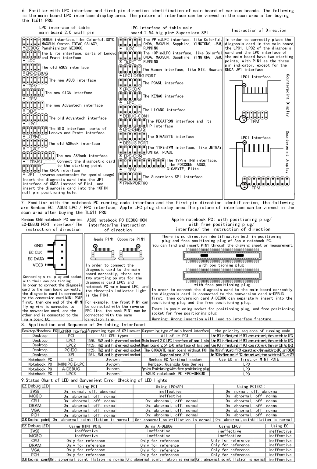
Manuals
This is the English manual for the TL611Pro but is very similar to the TL631Pro.
Page 1 of 2
Page 2 of 2