- Updated to [OpenWrt Wiki] OpenWrt 21.02.1 - Service Release - 25 October 2021
- This is currently on for pre-DSA firmwares, but I am sure it can be adapted
- The BT Home Hub 5A WiFi driver is not capable of bridge mode so we use Client mode and this is why we have to use RelayD to perform a type of masquerading on the WiFi client IP.
- I do not know if the new DSA firmwares will allow proper bridging without RelayD
Disclaimer: This setup has not been tested with IPv6 or extensively tested in the wild apart from my setup here, so if you are relying on this being secure you need to test it yourself before putting it into service
The following instructions will turn your BT Home Hub 5A/Plusnet One OpenWRT router into a WIFI client which has the following features:
- NAT’d network on the Yellow LAN sockets (isolated)
- Bridged network on the Red LAN socket
- Guest network called ‘Clients’ on the 2.4GHz WIFI (isolated)
- Connect to your parent router via the 5GHz WIFI
- The NAT network is secured/isolated and cannot access you primary network, however it can access the internet.
- The Bridge network is isolated from the NAT network but can see all of your parent network and of course the internet.
- You can change the network that each Ethernet sockets belongs to by changing just the VLAN tag under the switch menu.
- The router will have 2 IP addresses
- 192.168.0.1 - Local IP address, DHCP range 192.168.0.x, this is the NAT'd network
- 192.168.1.2 - NAT Network IP
- 192.168.1.3 - Bridge Network IP
- The NAT network has all traffic to private IP addresses blocked (10.0.0.0/8, 172.16.0.0/12, 192.168.0.0/16) No other traffic is blocked i.e. internet
Why?
On my test bench where I work with client laptops and PCs i need a secure network so infected computers do not attack my computers with virus, but I also have a netowrk laser printer that is not wifi capable. So i connect my printer to the red socket on my primary network allowing me to print whilst i can use the yellow ethernet sockets for an isolated network for working on client machines.
This configuration can be adapted for your needs, some people might only want 'Bridge Mode' and by following my instructions you can have that. I quite like the fact you can change the setup of the networks by jsut changing the VLAN tags (except for the AP, i need to check this)
Requirements
- BT Home Hub 5A / Plusnet One
- Flashed with the latest version of OpenWRT (v18.06.2)
- Reset to defaults.
- I will refer to this as the OpenWRT router.
- Another router (OpenWRT or 3rd party)
- Must be connected to the internet.
- You can use another OpenWRT router like I have, but it is not required.
- I will refer to this as the Parent router.
- Ethernet cables
- PC with an Ethernet connection
PART 1 - Preparing the Routers
Here we are going to set the groundwork for this project.
Parent Router Configuration
- Getting Started
- Make sure your PC is not connected to the internet (i.e. disable the wireless) and then connect it to one of the OpenWRT router’s yellow Ethernet sockets by the Ethernet cable. The PC's network card should be set to DHCP.
- Power the router on.
- Login to the OpenWRT router (192.168.1.1). Do not set a password yet, you will thank me for this later.
- Set the admin IP and DHCP range of the parent router
- If your parent router IP is not 192.168.1.1 then change it's IP to 192.168.1.1 (for the purposes of making this tutorial easier)
- You might not need to do this depending on your parent router.
- Other IP addresses and IPs will work but are outside the scope of this tutorial and must not be the same IP or range range of the parent router.
- You need 2 static IPs, and for this tutorial we will use
- 192.168.1.2
- 192.168.1.3
OpenWRT Router Configuration
- Change the Admin IP of the OpenWRT router before we can begin. I will be using 192.168.2.1 for reasons that will become clear later (but you could use almost any IP/Range you wanted).
- Set (Network --> Interfaces --> LAN --> Edit --> General Settings --> IPv4 address) = 192.168.2.1
- Click ‘Save'
- Change the 'Save & Apply' button to 'Apply unchecked' and then click
If you get stuck see [OpenWrt Wiki] Change LAN IP in LuCI (to an IP on a different subnet)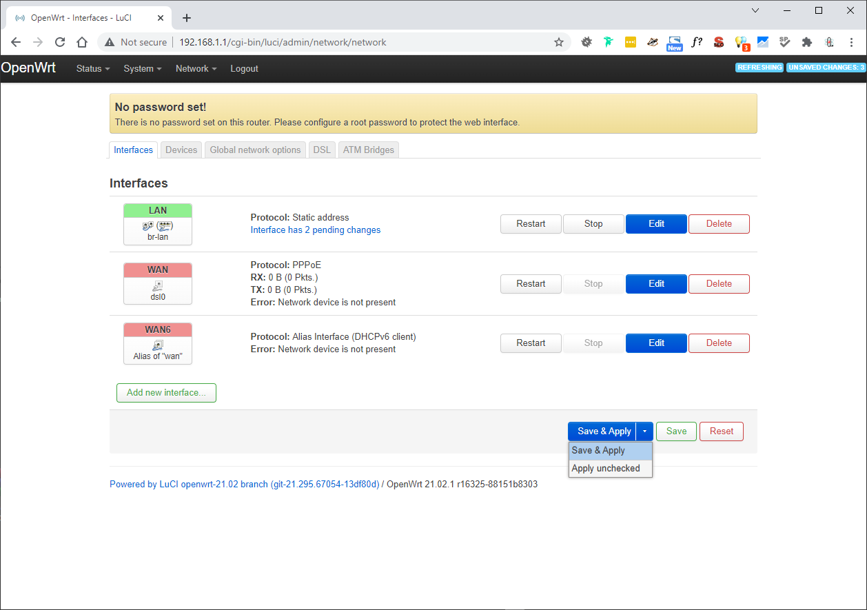
- If you just click 'Save & Apply' wait until the error message appears and click 'Apply unchecked'
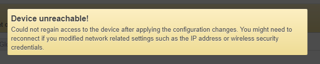
- Wait the 90 seconds and then when a message comes up saying ‘Device unreachable!’, power cycle the OpenWRT router (turn it off, wait 10 seconds and then turn it back on again)
- You might need to disable/enable your ethernet connection.
- The OpenWRT router will now load up on the new IP range/subnet and the IP on your network card will have changed to match the new network range/subnet.
- Login to the router on the new IP (192.168.2.1)
- Change hostname and local time
- Goto (System --> System --> General Settings)
- Hostname: officerouter
- You can pick a name of your choosing but it is easier to keep it like this for now while doing the tutorial.
- This prevents confusion if using other OpenWRT routers
- Timezone: Europe/London (this is correct for me)
- Hostname: officerouter
- Click 'Save & Apply'
- Goto (System --> System --> General Settings)
- Delete the following interfaces (Network --> Interfaces)
- WAN
- WAN6
- Delete the ATM Bridges (Network --> Interfaces --> ATM Bridges)
- There should only be one
- Delete all Wireless Configurations (Network --> Wireless)
- There are only 2 and are labelled as disabled
- Click 'Remove' for each wireless configuration
- Click 'Save & Apply'
- DSL Reboot Bug (BT Home Hub 5A / Plusnet One only)
- A watchdog bug was discovered which causes the hub to reboot between 24-48 hours if the hub is not connected to an active xDSL line. From Ebilan Forum
- To Fix: disable dsl_control service. If the DSL port is not going to be used, which it isnt with this configuration.
- Goto (System --> Startup)
- Find the line with dsl_control
- Click the 'Enabled' button (this disabled the service from the startup configuration.
- Click the 'Stop' button (this immediately stops the service.
- You do not need to click 'Save & Apply' for these settings to take affect.
PART 2 - Make the OpenWRT router a client of your 'Parent Router'
I am going to use the 5GHz radio because my parent router is a 5GHz router and this will give much better connection speed than the 2.4GHz.
- (Network --> Wireless --> Qualcomm Atheros A9880 802.11nac --> Scan) (radio0 / This is the 5G wireless card)
- Click on 'Join Network' next to your parent routers Wi-Fi network (for the purposes of this tutorial openwrt_5g)
- Fill in your connection details (NB: 'Replace wireless configuration' will wipe any configurations belonging to this radio so dont do it. You can see them on the ‘Wireless Overview’ page)

- WPA passphrase: Your 'Parent Routers' WiFi password for openwrt_5g
- Lock to BSSID
- If you only have 1 parent router and are not moving this router about (i.e. roaming) then this might be useful and a little extra security, but no good if you are using this image for your mates router etc.. So leave it off unless you know why you need it on.
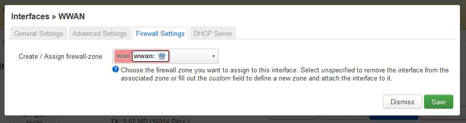
- 'Create / Assign firewall-zone' = unspecified
- we will alter the Firewall rules later
- you might see wan: (empty) if you are editing the connection and not creating a new one
- Click 'Submit'
- You have now been sent to Wireless Network: Client “openwrt_5g” (radio0.network1)
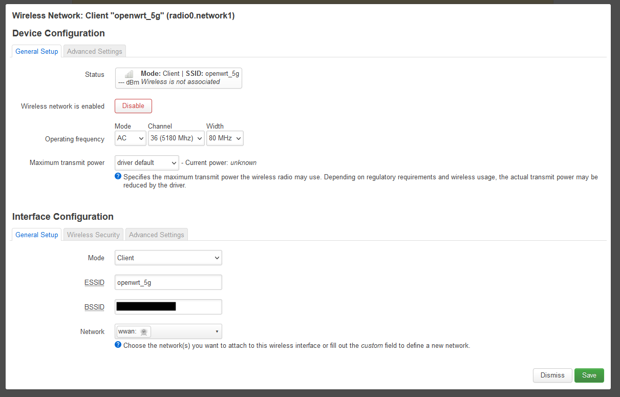
- (Interface Configuration --> Wireless Security --> Encryption) = WPA2-PSK/WPA3-SAE Mixed Mode (strong security) (or the encryption of your choice)
- Click ‘Save’
- Click ‘Save and Apply’
- Test the routers connection to the internet because it should be working now. This also assumes your 'Parent router' is on the internet.
- Goto (Network --> Diagnostics)
- Run a 'IPv4 Ping' test
PART 3 - Reconfigure the NAT Network (for secure clients)
We now are going to configure the OpenWRT to have a secure NAT'ed network and this will run on the yellow yellow LAN sockets. Make sure you follow each section below in order.
My parent WiFi SSID is openwrt_5g
Reconfigure the LAN and WAN Zone Firewall Zones
These rules only need a few changes because they are already geared up for NAT and all of the preconfigured Firewall rules are applied to these zones so we should keep them for the NAT WIFI Client
We will be re-using the rules that are already present to preserve all of the preconfigured rules for extra security. They might not all be needed, however if you do not want any of them, then delete the rules and just add the new zones with the settings below.
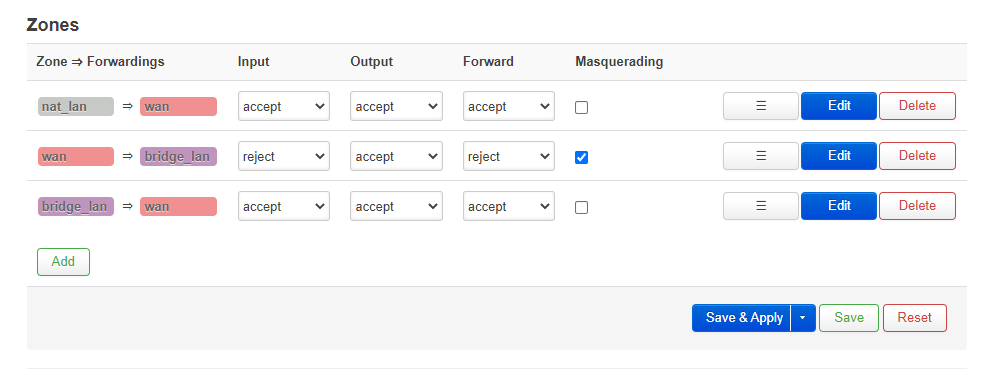
- Goto (Network --> Firewall --> Zones)
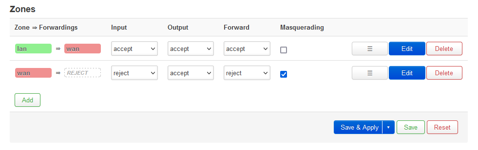
Edit LAN Zone
- Edit lan zone with the following settings

- (The settings below should be the same as the default rules (i.e. just changing the name))
- Click 'Save'
- Click 'Save & Apply'
Edit WAN Zone
- Edit wan zone with the following settings

- Only the MSS clamping should be different from the default rules and the name. This is to do with packet length and DSL traffic
- Click 'Save'
- Click 'Save & Apply'
Create new LAN Interface for Client NAT
- Goto (Network --> Interfaces)
- 'Add a new interface' called nat_lan

- Click 'Create interface'
- Fill in the following for ‘Interfaces >> NAT_LAN’ page
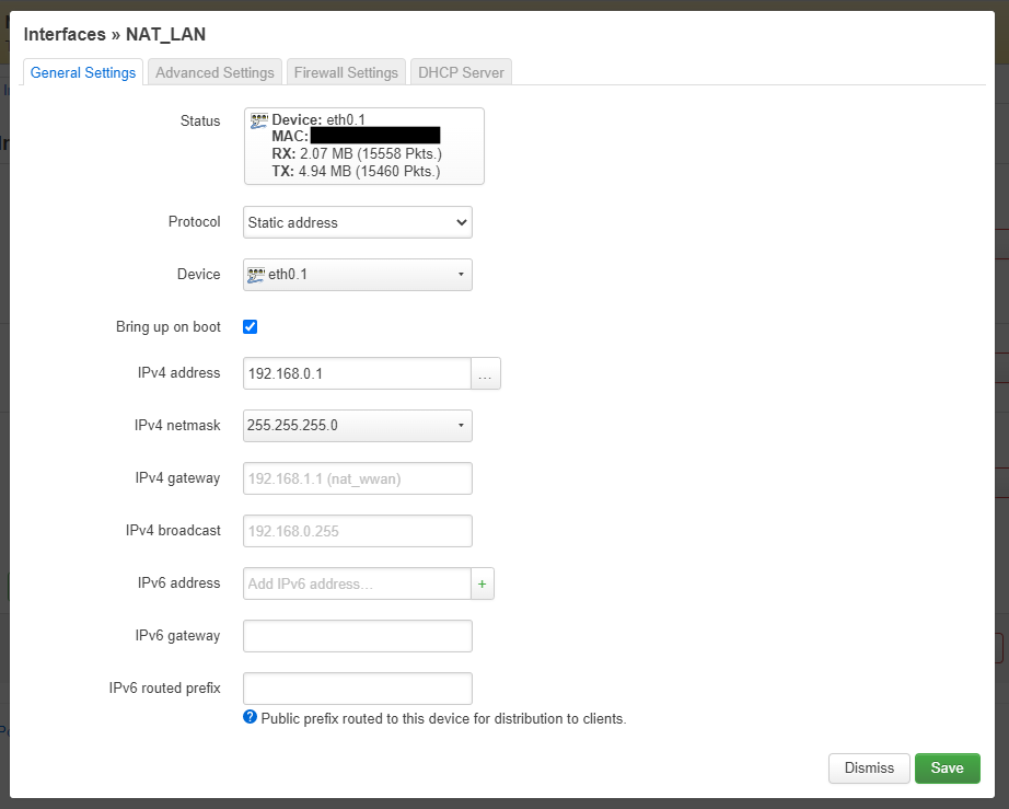
- Remember the 'Parent Router' is on the range 192.168.1.1
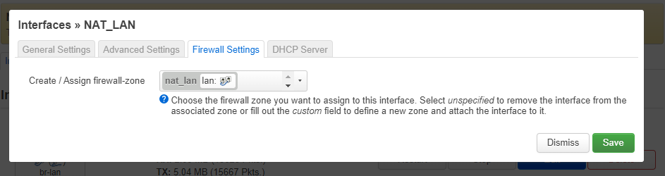
- On the Firewall tab ‘Create /Assign firewall-zone’ = nat_lan
- Leave everything else as it is on the ‘Interfaces >> NAT_LAN’ page
- Click 'Save'
- Edit to the interface NAT_LAN
- Enable the DHCP server by clicking on 'Setup DHCP Server'
- Click 'Save'
- Click 'Save & Apply'
- Edit the interface (Network --> Interface --> WWAN)
- Change the protocol to Static address
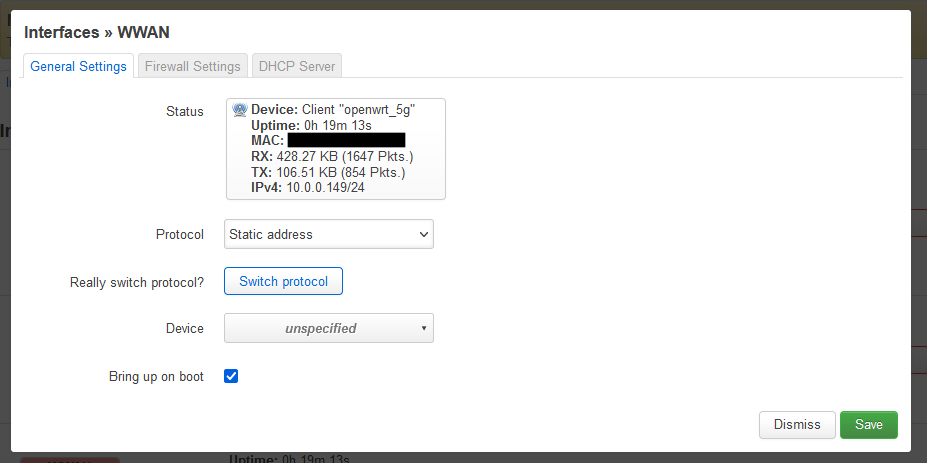
- Click 'Switch Protocol'
- After clicking 'Switch Protocol' the WWAN page will refresh and you should fill in the following information
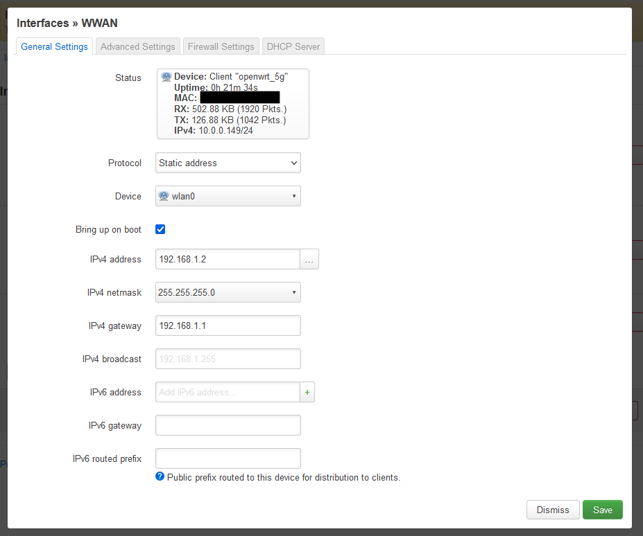
- Device = wlan0 (Wireless Network: Client “openwrt_5g”nat_wwan)

- IPv4 address = 192.168.1.2 (remember my parent router is on the range 192.168.1.1)
- Device = wlan0 (Wireless Network: Client “openwrt_5g”nat_wwan)
- Goto the 'Advanced Settings' Tab
- Use custom DNS servers = 192.168.1.1

- Do not setup a DHCP server
- Goto the Firewall tab
- ‘Create /Assign firewall-zone’ = wan (should already be set as shown below)
- Leave everything else as it is
- Click Save
- Click 'Save & Apply'
Finalise Settings
- Now logon on to the router on 192.168.0.1 (you will have to set a manual IP in your network card)
- Check Connections via the following methods so we know we can access the OpenWRT router via 2 different methods. A second PC is useful here so you can test all connection methods without connecting and reconnecting your PC to multiple Ethernet ports with different IPs. If all has been setup correctly you should have access as shown below:
- Access OpenWRT router (192.168.0.1) via the yellow sockets on the OpenWRT router
- Access the internet via the yellow sockets on the OpenWRT router
- The Red socket on the OpenWRT router will not work at this point
- Access OpenWRT router (192.168.1.2) from the parent router network by either using the parent router Ethernet sockets of WiFi
- NB: Sometimes the IP will not renew on your PC so stop and start your network card to fix this.
- Backup your settings before we do anything else as a precaution
- Goto (System --> Backup / Flash Firmware)
- Delete the interface LAN
- Because we used 192.168.2.1 range for the old LAN interface we can easily delete it now, and just use the 192.168.0.1 range without having to go around the houses to swap the IP ranges over.
- Goto (Network --> Interfaces)
- Click 'Delete' and the LAN will be marked for deletion.
- Change the 'Save & Apply' button to 'Apply unchecked' and then click it.
- When a message comes up saying ‘Device unreachable!’, power cycle the router
- You might need to disable/enable your ethernet connection.
- Backup your configuration again and put it somewhere safe
- System --> ‘Backup / Flash Firmware
You have now configured your OpenWRT router to act as a WiFi client on your parent network via NAT on the yellow ethernet sockets with the interfaces and firewall rules are clearly labelled
PART 4 - Bridge WIFI Client (Wireless Ethernet Bridge)
This allows us to extend your parent network to your OpenWRT router. This will work alongside the NAT WiFi Client network we just configured or as a standalone by just using the red socket on a separate VLAN.
- relayd does not currently support IPv6
- relayd is NOT a true bridge
- How the 'Relay Bridge' works
- Masquerade = NAT.
- Not all OpenWRT devices have bridge capable drivers.
- The 'Relay Bridge' bridges 2 networks together because OpenWRT cannot do this natively.
- The 'Relay Bridge' masquerades the Interface IP on the donour network (i.e. WWAN) to be able to pass and route the traffic to the target network (i.e. BRIDGE_LAN).
- The 'Relay Bridge' allows some broadcast traffic through the networks, but it is limited to DHCP (I think).
- The local addresses on the BRIDGE_LAN even though they are on the same subnet as the WWAN, the traffic is always masqueraded through the WWAN IP.
- This behaviour can cause issues with routing specific IPs with kit such as pfSense being given the WWAN Ip and not the Device IP.
Background
According to OpenWRT, the open source drivers of this router they use do not support native Client Bridge so you have to use a software workaround using relayd which required the following packages to be installed:
- luci-proto-relay
- relayd
A useful video to watch, the OpenWRT version is an old version but it should help with any issues, How to set up openwrt to be a wireless receiver [Bridge] with Relayd - YouTube
Install Packages
Extra software/packages are required to bridge the networks. We will now install them.
- Goto (System --> Software)
- Click ‘Update lists’
- In filter enter luci-proto-relay
- Click ‘Download and install package’
- When you click the button, luci-proto-relay will be installed and it will also bring down and install relayd as a dependency.
- Reboot the router.
Create the Firewall Zone (BRIDGE_LAN)
We now need to create a firewall zone for the bridge LAN network
- Goto (Network --> Firewall --> Zones)
- Add a new Firewall Zone

- Click 'Save'
- Click 'Save & Apply'
Create BRIDGE_LAN Interface
The bridge network needs interfaces creating so the router know where to talk to the network.
- Goto (Network --> Interfaces)
- Add new interface

- Click 'Create interface'
- There is nothing to fill in here for unmanaged.

- Click 'Save'
- Click 'Save & Apply'
- Edit the BRIDGE_LAN interface again
- On the firewall settings tab: `Create / Assign firewall-zone` = bridge_lan (empty)
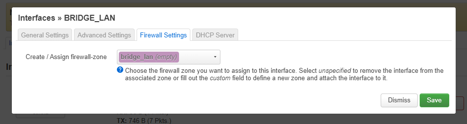
- Click 'Save'
- Click 'Save & Apply'
Create BRIDGE_RELAY Interface
This is the invisible routing node that relayd provides but it does appear as an interface.
- Goto (Network --> Interfaces)
- Add new interface called bridge_relay
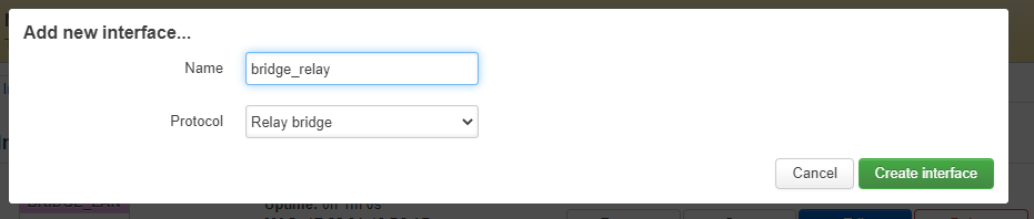
- Click 'Create interface'
- Fill in the following on the ‘Interfaces – BRIDGE_RELAY’ page
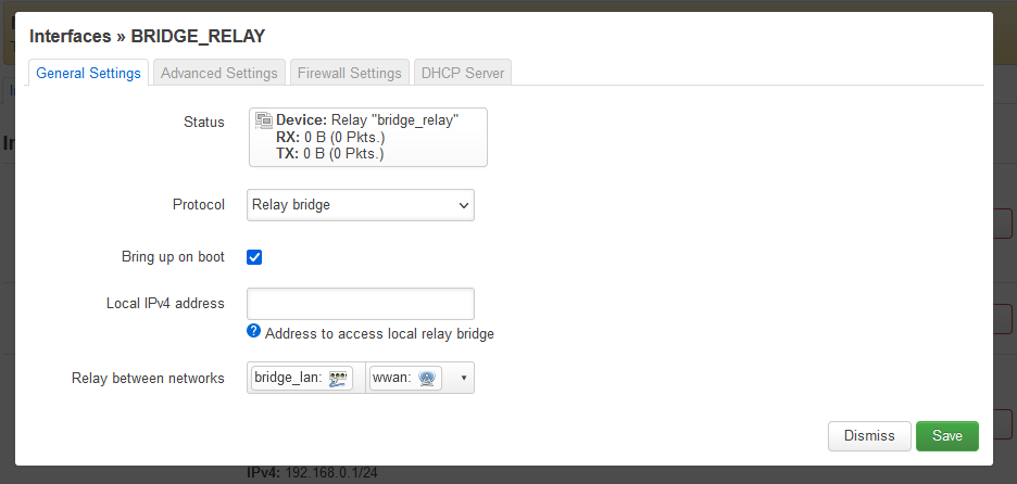
- Do not fill in ‘Local IPv4 address’ as this will break this configuration.
- On the firewall settings tab: `Create / Assign firewall-zone` = bridge_lan

- Click 'Save & Apply'
- Click 'Save'
Finalise Settings
- Power cycle the OpenWRT router, this will apply the settings above
- Once rebooted connect to the red port and make sure you can browse the internet
- Your Interfaces should now look like this

- Your Zones should now look like this
Cannot access router from BRIDGE_LAN
- With this configuration you cannot access the router from the BRIDGE_LAN
- If you add an IP to the BRIDGE_RELAY or BRIDGE_LAN routing will break.
- If anyone works out the solution please let me know.
(optional) Temporarily disable BRIDGE_RELAY and use Ethernet for BRIDGE_LAN
If you have spent time configuring your router and find that you need to connect BRIDGE_LAN to your 'Parent Network' via the ethernet because of a bad WiFi signal or you just need more speed then that is easy to do.
You cannot have the router sending traffic to the 'Parent Network' whilst getting the 'Parent Network' from the ethernet as this will casue a broadcast storm so we need to correct this with the minimum intervention.
- In the VLANs section below you need to make sure you have more than one ethernet socket available on the BRIDGE_LAN network
- Login to your router via the NAT_LAN network
- Goto (Network --> Interfaces --> BRIDGE_RELAY --> EDIT --> General Settings)
- Remove bridge_lan and wwan from 'Relay between networks'
- Click 'Save'
- Click 'Save & Apply'
- Reboot the router
Part 5 – Network Isolation
I will be investigating VLANs and how to apply them to my 'Primary Router' and it's WiFi so this network is further isolated.
I now need to isolate the NAT network (nat_lan) from my main network because both networks are present on the OpenWRT router, and OpenWRT will always try and figure out the best route for all traffic which is undesirable in this case.
This is different from Wireless client isolation.
Solution
The fix is simple, we need to configure the Firewall Traffic Rules by adding some additional rules.
Adding a Firewall Rule
- Goto (Network --> Firewall -->Traffic Rules)
- Click 'Add'
- Fill in the details for each rule (see below)
- Click 'Save'
- When they are all don, click 'Save & Apply'
- Reboot the router
The Firewall Traffic Rules
- A copy and paste list is at the bottom for those of you more familiar with OpenWrt
- Add each following rules, in order, into LuCi.
- The following rules need to be added at the top of the 'Firewall - Traffic Rules' List (LuCi)
- When you re-order rules in LuCi you need to click 'Save & Apply'
Block 'Parent Network' IPs
Currently if you ping an IP address on the 'Parent Network' from the NAT_LAN network you will get a response because the device on the 'Parent Network' will only see the IP address of the officerouter (192.168.1.2) and will not know the difference (IP Masquerading). Not only can you ping devices, you can make connections for such things as file sharing and in these modern times if an encryption malware can see a share, it will encrypt it.
- Block - WAN - Class A IPs
- Name: Block - WAN - Class A IPs
- Protocol: Any
- Source zone: nat_lan
- Destination zone: wan
- Destination address: 10.0.0.0/8
- Action: reject
- All the other options should be left as is
- Block - WAN - Class B IPs
- Name: Block - WAN - Class B IPs
- Protocol: Any
- Source zone: nat_lan
- Destination zone: wan
- Destination address: 172.16.0.0/12
- Action: reject
- All the other options should be left as is
- Block - WAN - Class C IPs
- Name: Block Parent Network - C Range
- Protocol: Any
- Source zone: nat_lan
- Destination zone: wan
- Destination address: 192.168.0.0/16
- Action: reject
- All the other options should be left as is
Allow LuCI from the WAN
These rules just allow access to the officerouter's LuCI from the 'Parent Network' via the WAN route on 192.168.1.2
- Allow - WAN - LuCI (HTTP)
- Name: Allow - WAN - LuCI (HTTP)
- Protocol: TCP
- Source zone: wan
- Destination zone = Device (input)
- Destination address: 192.168.1.2
- Destination port: 80
- Action: accept
- All the other options should be left as is
- Allow LuCI (HTTPS) - NAT Network IP
- Name: Allow LuCI - NAT Network IP
- Protocol: TCP
- Source zone: wan
- Destination zone: Device (input)
- Destination address: 192.168.1.2
- Destination port: 443
- Action: accept
- All the other options should be left as is
- Allow SSH - NAT Network IP
- Name: Allow SSH - NAT Network IP
- Protocol: TCP
- Source zone: wan
- Destination zone: Device (input)
- Destination address: 192.168.1.2
- Destination port: 22
- Action: accept
- All the other options should be left as is
Firewall Rules (Copy and Paste)
This a copy on the whole file (/etc/config/firewall) to make things easier and quicker.
Once you have updated your firewall config reboot your router.
config defaults
	option input 'ACCEPT'
	option output 'ACCEPT'
	option forward 'REJECT'
	option synflood_protect '1'

config zone
	option input 'ACCEPT'
	option output 'ACCEPT'
	option forward 'ACCEPT'
	option name 'nat_lan'
	list network 'nat_lan'

config zone
	option name 'wan'
	option input 'REJECT'
	option output 'ACCEPT'
	option forward 'REJECT'
	option masq '1'
	list network 'wwan'

config forwarding
	option dest 'wan'
	option src 'nat_lan'

config rule
	option src 'nat_lan'
	option target 'REJECT'
	option dest 'wan'
	list dest_ip '10.0.0.0/8'
	option name 'Block - WAN - Class A IPs'
	list proto 'all'

config rule
	option src 'nat_lan'
	option target 'REJECT'
	option dest 'wan'
	list dest_ip '172.16.0.0/12'
	option name 'Block - WAN - Class B IPs'
	list proto 'all'

config rule
	option target 'REJECT'
	option src 'nat_lan'
	option dest 'wan'
	list dest_ip '192.168.0.0/16'
	option name 'Block - WAN - Class C IPs'
	list proto 'all'

config rule
	option target 'ACCEPT'
	option proto 'tcp'
	option dest_port '80'
	option src 'wan'
	list dest_ip '10.0.0.3'
	option name 'Allow - WAN - LuCI (HTTP) '

config rule
	option target 'ACCEPT'
	option proto 'tcp'
	option dest_port '443'
	option src 'wan'
	list dest_ip '10.0.0.3'
	option name 'Allow - WAN - LuCI (HTTPS)'

config rule
	option target 'ACCEPT'
	option src 'wan'
	option proto 'tcp'
	option dest_port '22'
	list dest_ip '10.0.0.3'
	option name 'Allow - WAN - SSH'

config rule
	option name 'Allow-DHCP-Renew'
	option src 'wan'
	option proto 'udp'
	option dest_port '68'
	option target 'ACCEPT'
	option family 'ipv4'

config rule
	option name 'Allow-Ping'
	option src 'wan'
	option proto 'icmp'
	option icmp_type 'echo-request'
	option family 'ipv4'
	option target 'ACCEPT'

config rule
	option name 'Allow-IGMP'
	option src 'wan'
	option proto 'igmp'
	option family 'ipv4'
	option target 'ACCEPT'

config rule
	option name 'Allow-DHCPv6'
	option src 'wan'
	option proto 'udp'
	option src_ip 'fc00::/6'
	option dest_ip 'fc00::/6'
	option dest_port '546'
	option family 'ipv6'
	option target 'ACCEPT'

config rule
	option name 'Allow-MLD'
	option src 'wan'
	option proto 'icmp'
	option src_ip 'fe80::/10'
	list icmp_type '130/0'
	list icmp_type '131/0'
	list icmp_type '132/0'
	list icmp_type '143/0'
	option family 'ipv6'
	option target 'ACCEPT'

config rule
	option name 'Allow-ICMPv6-Input'
	option src 'wan'
	option proto 'icmp'
	list icmp_type 'echo-request'
	list icmp_type 'echo-reply'
	list icmp_type 'destination-unreachable'
	list icmp_type 'packet-too-big'
	list icmp_type 'time-exceeded'
	list icmp_type 'bad-header'
	list icmp_type 'unknown-header-type'
	list icmp_type 'router-solicitation'
	list icmp_type 'neighbour-solicitation'
	list icmp_type 'router-advertisement'
	list icmp_type 'neighbour-advertisement'
	option limit '1000/sec'
	option family 'ipv6'
	option target 'ACCEPT'

config rule
	option name 'Allow-ICMPv6-Forward'
	option src 'wan'
	option dest '*'
	option proto 'icmp'
	list icmp_type 'echo-request'
	list icmp_type 'echo-reply'
	list icmp_type 'destination-unreachable'
	list icmp_type 'packet-too-big'
	list icmp_type 'time-exceeded'
	list icmp_type 'bad-header'
	list icmp_type 'unknown-header-type'
	option limit '1000/sec'
	option family 'ipv6'
	option target 'ACCEPT'

config rule
	option name 'Allow-IPSec-ESP'
	option src 'wan'
	option proto 'esp'
	option target 'ACCEPT'
	option dest 'nat_lan'

config rule
	option name 'Allow-ISAKMP'
	option src 'wan'
	option dest_port '500'
	option proto 'udp'
	option target 'ACCEPT'
	option dest 'nat_lan'

config rule
	option name 'Support-UDP-Traceroute'
	option src 'wan'
	option dest_port '33434:33689'
	option proto 'udp'
	option family 'ipv4'
	option target 'REJECT'
	option enabled '0'

config include
	option path '/etc/firewall.user'

config zone
	option name 'bridge_lan'
	option input 'ACCEPT'
	option output 'ACCEPT'
	option forward 'ACCEPT'
	list network 'bridge_lan'
	list network 'bridge_relay'

config forwarding
	option src 'bridge_lan'
	option dest 'wan'

config forwarding
	option src 'wan'
	option dest 'bridge_lan'
PART 6 – Guest WiFi called 'clients'
To get the most out of this tweaked OpenWRT router I am now going to add a guest WiFi network called 'Clients' which will be attached to the NAT network affording it all of the same isolation as that network.
We need to create a an AP on the 2.4GHz kit and bridge it to the NAT network
- Goto (Network --> Wireless --> Wireless Overview --> Atheros AR9287 802.11bgn (This is the 2.4GHz WiFi card / radio1 / wlan1) --> Add
- Configure as follows:
- (Interface Configuration --> General Setup)

- Mode = Access Point
- ESSID = clients
- Network = nat_lan
- WMM Mode: ticked
- (Interface Configuration --> Wireless Security)
- Encryption = WPA-PSK/WPA2-PSK Mixed Mode (medium security) (Good for Legacy devices)
- Or the encryption of your choice
- Cipher = auto
- key = Your password you want for the client network
- Don't use the password on the router because this password will be given out to the public and will be changed often.
- Encryption = WPA-PSK/WPA2-PSK Mixed Mode (medium security) (Good for Legacy devices)
- (Interface Configuration-->Advanced Settings-->Isolate Clients) = Ticked
- (Interface Configuration --> General Setup)
- Click 'Save'
- Click 'Save & Apply'
- You are now returned to the 'Wireless Overview' page, enable the Clients network by clicking on the 'Enable' button for that network. (if not already enabled)
- You will notice you can connect to the WiFi but not get an IP address. Follow Part 7 below to fix this.
Part 7 - Bridge a WiFi node to a LAN network
Background to this issue
In pre OpenWrt 20.00/pre-DSA we were able to join the eth0.1 and wlan1 networks directly with in the nat_lan interface but this now not currently possible because it requires extra coding to be implemented in OpenWrt 20.00+ by the OpenWrt team, if ever.
These settings were located at (Network-->Interfaces-->NAT_LAN (br-nat_lan)-->Edit -->Common Configuration-->Physical Settings)

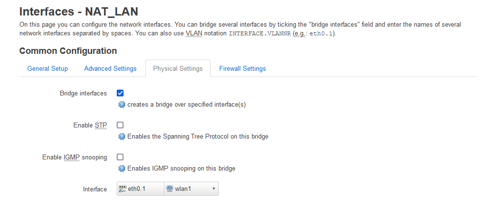
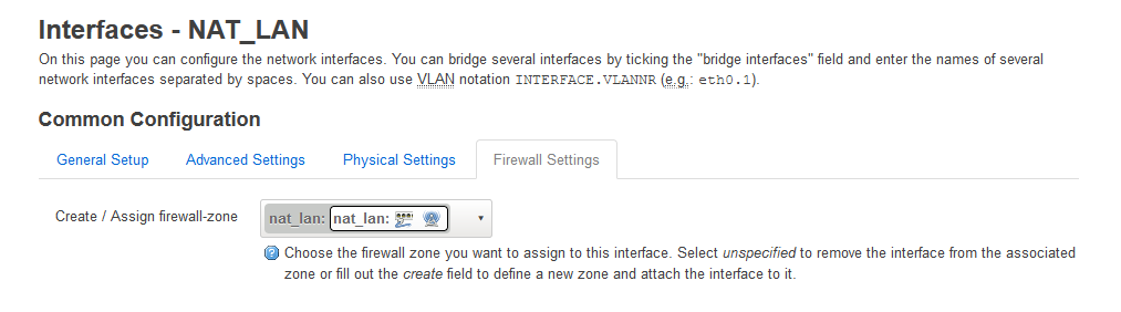
It should be noted when you try and setup a bridge device (Network-->Interfaces-->Devices) you are told that you cannot bridge WiFi and ethernet as you once did. Look at the 'Bridge ports' dropdown.
To resolve the missing bridge functionality we have to change the nat_lan device from eth0.1 to br-lan which also sort of follows the rule above. You cannot connect the WiFI to the following devices and have any routing happen. I also thinky the device must be a 'Bridge Device'.
- br-lan.1
- br-lan.2
- eth0 - Not tried this
- eth0.1
- eth0.2
Solution 1 (Easy)
- Goto (Network-->Interfaces)
- Edit the NAT_LAN
- Change the Device from eth0.1 to br-lan
- Click 'Save'
- Click 'Save & Apply'
- Traffic will now flow from the wireless on wlan0. My understanding that this traffic by default on br-lan should be on vlan1 so should still be isolated from eth0.2
- Rebooting the Router several times can sometimes help. It possible it to do with assigning new MAC addresses (my guess)
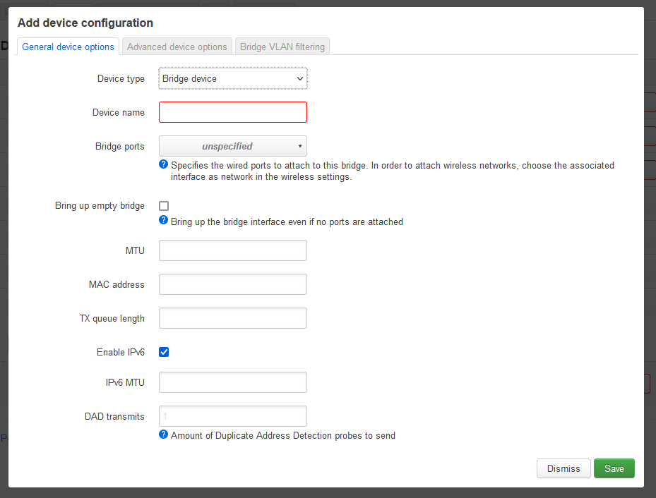
Solution 2 (Manual)
We are going to create a new 'Bridged device' (Virtualised Interface) that we can use to sit the WiFi and LAN on.
- There is currently a bug where if I delete br-lan and use br-nat_lan (or other name) to connect to eth0.1 then routing on the ethernet stops. This could well be to do with the migration to DSA and that br-lan is hardcoded somewhere to talk to eth0.1 so only use the method below for other VLANs and leave br-lan as is. Maybe a MAC addresses issue.
- You cannot have 2 'Bridge devices' on the same 'Bridge port(s)' as it breaks routing.
- You cannot have a 'Client mode' and an 'AP point' defined on the same Wireless interface, this breaks routing.
- Goto (Network --> Interfaces --> Devices)
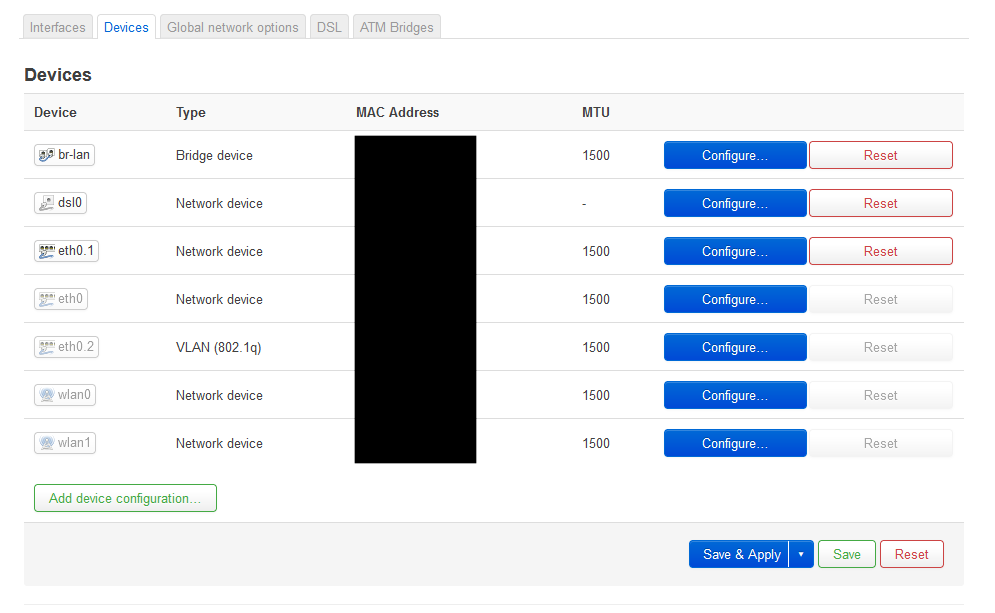
- Click 'Add device configuration'
- Device type: Bridge device
- Device name: br-nat_lan
- Bridge ports: eth0.1
- Click 'Save'
- Goto (Network --> Interfaces -->Interfaces)
- Edit NAT_LAN
- Change the Device to br-nat_lan

- Click Save
- Goto (Network --> Interfaces --> Devices)
- Click on the 'Reset' button for the br-lan device
- This will effectively remove the device
- You cannot have 2 'Bridge devices' on the same physical interface.
- Click on the 'Reset' button for the br-lan device
- Goto (Network --> Wireless --> your 'clients' network --> Edit --> Interface Configuration --> General Setup --> Network)
- change the network to br-nat_lan
- Click 'Save'
- Click 'Save & Apply'
- Reboot
Notes
- You can create multiple interfaces with different names such as br-bridge_lan and put these on other interfaces such as eth0.2
- You can use this method to add WiFi on the the BRIDGE_LAN network. In fact I have add both 24.GHz and a 5GHz Wifi AP point onto my router.
PART 8 - VLAN Assignments (Optional)
Name the VLANs for easy management
- Goto (Network --> Switch --> VLANs on "switch0" (Lantiq XRX200 Switch))
By changing the VLANs to which the ethernet socket belongs to you can change their network assignment.
There are 2 options to select from and just depends on what configuration your want
Option 1
All of the yellow sockets are on your secure 'clients' network and the red socket is on your private network.
- Goto (Network --> Switch --> VLANs on "switch0" (Lantiq XRX200 Switch))
- Fill in the description fields in as follows and you do not need to change the Port assignments.

Option 2
All of the yellow sockets are on your 'Private' network and the red socket ins on the 'clients network
- Goto (Network --> Switch --> VLANs on "switch0" (Lantiq XRX200 Switch))
- Fill in the description fields and also change the port assignments to match below.

PART 9 – Final configuration
If all is working set your admin password
- Set your admin password
- Goto (System --> Administration --> Router Password)
- This is very important now the unit is Configured.
- I prefer to use the Admin password on the card that (BT Homehub 5A / Plusnet One) router comes with. It makes things a lot easier.
- Don’t forget to click 'Save & Apply'
- Set the Wireless country code to your region
- In each of the wireless configurations do the following to set your region.
- Goto (Network-->Wireless-->SSID: whatever-->Edit-->Device Configuration-->Advanced Settings-->Country Code)
- Set your Country code to your region
- see Install OpenWrt on a BT Home Hub 5 / Plusnet One Router | QuantumWarp
- (Optional) WPS on the clients network
- (Optional) Force HTTPS (the browsers might stat upgrading if you use a domain name rather than IP)
- (Optional) Add SFTP server to make things much easier
- (Optional) LEDs (System --> LED Configuration)
- Edit wifi LED
- Name: NAT_LAN Activity
- LED Name: blue:wireless
- Trigger Network device activity (kernel: netdev)
- Device eth0.1 (Switch VLAN: "eth0.1" (nat_lan)) - This seems flacky. If I save and resave the this LED setting then monitoring will occur, other wise nothing. There might be a fault with the trigger.
- -- Trying br-lan
- Device br-lan (Bridge: "br-lan" (nat_lan)) while I cannot access eth0.1 directly.
- Trigger Mode: Transmit, Receive
- Edit dsl LED
- Name: BRIDGE_LAN Activity
- LED Name: red:broadband (matches the red socket)
- Trigger Network device activity (kernel: netdev)
- Device eth0.2 (Switch VLAN: "eth0.2" (bridge_lan)
- Trigger Mode: Transmit, Receive
- Edit dimmed
- Name: dimmed
- LED Name: dimmed
- Trigger: Always on (kernel: default-on)
- Default state: unticked
- Edit wifi LED
- (Optional) installed_packages.txt
- Add /etc/backup/installed_packages.txt to config backup
- make sure you run sysupgrade -k -u -b to get an update package with the installed_packages.txt so you can keep it as a full reference archive
PART 10 – Verify Security
I advise you to run through the following test to make sure that the different networks are blocked from each other as they should be before trusting this setup.
- On the default setup you can access the OpenWRT via the following methods
- 192.168.0.1 - From the yellow ethernet sockets and the 'Clients' WiFi
- 192.168.1.2 - From the parent network
- 192.168.1.3 - From the parent network
- 192.168.1.2 and 192.168.1.3 are unavailable via the red socket
Notes
RelayD LuCI Workaround Notes??
This are notes for a workaround for BT Home Hub 5A / Plusnet One to be able to access the LuCI admin and SSH services on the OpenWRT router on the bridged network.
- Why you cannot access admin IP on a network using relayd
- By default on OpenWRT all interface IP are bound to the routers services i.e. LuCI on port 80, SSH on port 22.
- When you use relayd, the interfaces that you bridge between have this direct access removed and traffic is piped through the relay instead so the OpenWRT services are not bound to the IP
- This means if you try and access OpenWRT admin (or other services) through 192.168.1.3 either through the Red Ethernet socket or from the parent network you will not be able to connect because it is relayd doing the routing and not the OpenWRT core so effectively you cannot see these services and the traffic is just lost/dropped as it has no destination to go to, the services do not exist on the IP 192.168.1.3
- Zones are also ignored for routing (even thought all the bridge interfaces need to be in the same zone for the bridge to work)
- Solution
- The wan interface sits on the same physical hardware (wlan0) so we can use the wan zone to allow the traffic through to the IP 192.168.1.3
- So if you examine the rules above the only real difference is the source_zone
- I am not sure if this is a good thing or causes any issues and is why I say it is optional.
- You can always access the OpenWRT admin via 192.168.1.2 along with all other services.
- 192.168.1.2 and 192.168.1.3 are still unavailable via the red socket
- Solution 2
- Access through the clients WiFi?
General
- All device names can be found in (System-->Realtime Graphs-->Traffic)
Tutorials
- OpenWRT - WiFi Bridge (LAN to LAN WiFi repeater/extender) - YouTube (Van Tech Corner) In this video, we are going to setup WiFi bridge to extend the LAN network wirelessly on OpenWRT LuCI with relayd package. This is also know as Wi-Fi extender / repeater / bridge configuration. As a result, you will have another extended network via WiFi that has the same LAN IP range/subnet with the primary router.
- Setup LAN/WLAN Bridge with OpenWrt (LuCI) (updated) - Nerd Quickies - A tutorial using relayd as a base.
- OpenWrt: Set up a Basic Network Including WiFi Bridge, IP Address, DHCP | linuxscrew - This article will show you how to configure a basic network with WiFi Bridging, DHCP on a fresh install of OpenWrt – with explanations and screenshots.
Firewall
- Start reading here for firewall information
- Masquerade is the most common form of SNAT, changing the source of traffic to WAN to the router's public IP. SNAT can also be done manually.
- OpenWRT firewall process the rules and then stops when it finds a matching rule (from top down)
- https://oldwiki.archive.openwrt.org/doc/uci/firewall (This is where you need to read to understand Firewall Rules)
- "The UCI Firewall provides a configuration interface that abstracts from the iptables system to provide a simplified configuration model"
- "The first rule that matches is executed, often leading to another rule-chain until a packet hits either ACCEPT or DROP/REJECT"
- Rule Process Order (openwrt firewall process the rules and then stops when it finds a matching rule) (double check order below!!!)
- openwrt selects the firewall zone
- then processes the firewall rules (Top to Bottom)
- then process the zone default rule set
- When browsing the internet the domain is the destination not the parent router gateway address. So it is the final destination that is key, not the route the packet takes so dont get mixed up thinking the gateway is the destination.
- The firewall configurator in openwrt (UCI Firewall) is just a 'GUI' to configure the firewall rules
- CIDR Format
- 192.168.1.1/24 = CIDR format
- IPv4 Private Address Space and Filtering - American Registry for Internet Numbers
- What does the IP "192.168.1.1/24" indicate? - Server Fault
- networking - CIDR for Dummies - Server Fault
CIDR Dotted Quad
/8 255.0.0.0
/16 255.255.0.0
/24 255.255.255.0
/32 255.255.255.255 - Why this private IP only range 172.16.0.0 - 172.31.255.255 ? - 64727 - The Cisco Learning Network - This has CIDR examples
- What does 0.0.0.0/0 mean? : Reddit
- 192.168.1.1/32 usually refers to asingle IP address
- IP Filtering in Canvas - This is a noce easy read on IP address and CIDR format.
- openwrt can only route between zones, can only apply rules between zones i.e. when routing
- Cannot apply Firewall rules on bridge network because traffic does not change zones, it is all on the same network/zone 192.168.1.x , relay is between bridge_lan and bridge_wwan. this is a bridge between 'network interfaces' and not 'physical devices'
- OpenWRT firewall rules will only work when traffic is transitioning between zones
- You can apparently control traffic on the same zone using netfilter but this seems complicated and I have not done this.
- Firewall needs an interface to have an IP to be able to route traffic
- DROP vs REJECT
- Drop = Request timed out (with this option you get no positive feedback)
- Reject = Destination host unreachable (If you use this method you can easily see if the firewall is blocking the traffic.)
- I am using REJECT in this setup - With a REJECT I can see instantly that the firewall has blocked the traffic and if I get a 'Request Timed Out' that means the target does not exist on the router and or cannot be routed to but if I get 'Destination port unreachable' then I know the firewall is actively blocking the traffic.
- Drop versus Reject (This helped me decide)
- linux - REJECT vs DROP when using iptables - Server Fault
- Always reboot after making firewall changes because they 'do not always get applied correctly' / 'IPTABLES need to be flushed'. If you think a rule should be working but it is not this is will likely fix it. I think it is because routes are cached. You can also use the command line to clear the cache.
- If a rule was blocking traffic and then you remove the rule traffic will start flowing, however if trafic was allowed and then blocked you will find the traffic still flows because of rule caching (i am guessing about this being the cause)'
- Firewall rules only work between zones so cannot be used on the same zone.
- You can use Netfilter/iptables to specify network rules but I am not sure how to do this (see link)
- A firewall rule controls what happens when a packet transitions from one device to another which crosses a zone boundary. Or to put it another way when a packet transitions from one zone to another. I.e. this is why Nat is enabled on the firewall zone because this is the point you want to NAT IP address between the interfaces and not in them because routing should be invisible to the interfaces.
- Adding Luci access from parent network
- Enabling remote SSH access on OpenWRT 12.09 - Real simple instructions on adding the required firewall rule
- networking - Can't connect via LuCI or SSH from WAN side network to Raspberry Pi 1B running OpenWRT 14.07 - Super User - Don’t forget to make sure the changes are applied
- Zone Controls:
- Zone / Name = The rule’s name
- Forwardings =
- aka Inter-Zone Forwarding which is also covered at the bottom of this list
- the icons explained in the Zones list because they are confusing
- 1st / left = this is the networks in the zone (Covered Networks). Hover over the icon to see them. You will notice that all of these first icons all have the same name as the Zone.
- 2nd / right = Allow forwarding to these destination zones
- Input = default policy for traffic entering this zone
- Output = default policy for traffic leaving this zone
- Forward = describes the policy for forwarded traffic between different networks within the zone. I think this stops the zones talking to each other (isolates them)
- Masquerading = also known as - NAT (network-address-translation)
- This is why it is required for my network to work. It bridges the networks by the rule and also does NAT on them at the same time
- MSS Clamping =
- “A workaround used by some routers is to change the maximum segment size (MSS) of all TCP connections passing through links with MTU lower than the Ethernet default of 1500. This is known as MSS clamping.”
- https://en.wikipedia.org/wiki/Path_MTU_Discovery#Problems_with_PMTUD
- Translates DSL type packets to Ethernet sized packets to prevent errors occurring. So I would guess it is only needed on Ethernet ó DSL
- Covered Networks = those networks that have this rule applied
- Inter-Zone Forwarding = The options below control the forwarding policies between this zone and other zones. Basically what zones is this zone allowed to talk to and you can also control the traffic directions.
- My WWAN zone has the following rules + explanation
- Input – reject = blocks requests originating from outside
- Output = accept – allows communication started from inside to go out the network and consequent have a conversation with that endpoint
- Forward – reject = prevents any other networks on this zone
- Masquerading = on – to NAT the connection and allow routing
- MSS Clamping – not needed because the WWAN is an Ethernet type interface and not a DSL where the MTU size could be less than 1500
- Covered networks – just itself because this is the only zone that will need NAT’ing and is the main in/out route
- Allow forward to destination zones: = none
- Allow forward from source zones: = lan + redlan – these are my 2 ethernet networks
- The Beginner’s Guide to iptables, the Linux Firewall
Distributed Switch Archeitecture (DSA)
This is replacing swconfig which uses the LuCI item (Network --> Switch)
- There is no migration path for targets that switched from swconfig to DSA. In that case, sysupgrade will refuse to proceed with an appropriate error message.
- [OpenWrt Wiki] DSA Mini-Tutorial - This DSA Mini-Tutorial explains how DSA works with OpenWrt.
- [OpenWrt Wiki] Converting to DSA - Some OpenWrt 21.02 (and newer) devices use DSA for configuring network interfaces. If you are upgrading your router to a firmware version that uses DSA, you should read this page.
- Mini tutorial for DSA network config - Network and Wireless Configuration - OpenWrt Forum - This is more a tutorial but is well explained and has pictures.
- VLANs in OpenWrt 21 | YouTube | OneMarcFifty
- The VLAN Configuration has changed in OpenWrt 21.02 - Bridge VLAN Filtering and Distributed Switch Architecture (DSA) change the way we configure the network segmentation in a Guest, IOT and LAN Network.
- A very informative video
- Assigning the WiFi to the right network is done
- https://www.youtube.com/watch?v=qeuZqRqH-ug&t=1250s
- Network --> Wireless --> [WiFi Network] --> Edit --> Interface Configuration --> General Setup --> Network
- [OpenWrt Wiki] Wireless Access Point / Dumb Access Point - Doesnt really cover 20.00+ at the minute.
- Any chance of updated "dumb" access point guide? - #3 by jaromanda - Network and Wireless Configuration - OpenWrt Forum
- Mini tutorial for DSA network config - Network and Wireless Configuration - OpenWrt Forum
- Bridging networks is not currently possbly like it was pre-DSA
- Wireless Bridge "different" than Wired - For Developers - OpenWrt Forum
- Any chance of updated "dumb" access point guide? - #7 by jow - Network and Wireless Configuration - OpenWrt Forum
Specifies the wired ports to attach to this bridge. In order to attach wireless networks, choose the associated interface as network in the wireless settings.
- Trying to create a bridge with two legs - Network and Wireless Configuration - OpenWrt Forum
- Is there a way of using VLANs to do this?
- You could use relayd to bridge the networks like I did for the bridge network.
- Install OpenWRT 21.02 & DSA VLAN Configuration for WAN Interface - YouTube (Van tech Corner) This video shows you how to configure DSA on your router (if present) and how to identify it it has DSA.
- HH5a snapshot with DSA - enabling red WAN port
- If anyone wishes to enable the red WAN port on HH5a using latest openwrt snapshot which does use DSA, here are the details
- This might be the only change needed when upgrading your HH5a to a firmware that supports DSA.
-
The vlan settings back in the days (eth0.1, eth0.2 and so on) where the
only way to separate the ports of the switch. With DSA the vlan hack
isn't required any longer. The whole idea of DSA is to expose each
switch port as a network device.
Mathias
Network
- You do not need an IP on the LAN interfaces; I have just left one on the NAT_LAN so I can access the router from its ‘internal’ network if there are issues upstream. If you convert this to ‘unmanaged’ everything will still work you just won’t be able to access the OpenWRT admin from the local network
- You can add VLAN tags by using the notation eth0 --> eth0.0 : eth0 --> eth0.1 etc... I am not sure if all interfaces support this. Certainly the Ethernet and DSL connections do. I.e. dsl.101 to allow BT and Plusnet to work
- The router needs an IP address to be able to route between networks. This is probably obvious.
- When routing between networks they must be in a different IP range to allow routing.
- I think by default interfaces are routed to VLAN.1 – not 100% about this but it seems the case. Could be me not doing things right.
- Interfaces are software endpoints that can sit on a physical interface to interact with it or simple be a bridge. These endpoints are exposed to the OpenWRT core/kernel. The interfaces are not representations of the hardware. Hardware is eth0, wlan0, etc..
Bridge Tutorials
- [OpenWrt Wiki] Wi-Fi extender / repeater / bridge configuration - An old article I think i used as reference
- Setup LAN/WLAN Bridge with OpenWrt (LuCI) (updated) - Nerd Quickies - A tutorial on setting up relayd.
- How to set up IPV6 with relay bridge - Network and Wireless Configuration - OpenWrt Forum - A tutorial on making a bridge using relayd and a BT Home Hub 5a.
WiFi/Wireless
- WMM Mode
- On the wireless interface WMM allows the use of faster speeds without it connections are crippled for some reason. Maybe it allows the use of faster frequencies 20/40/80 MHz….
- Is WMM a type of QoS?
- WMM (WiFi Multimedia) | Answer | NETGEAR Support
- You can add an ‘access point’ to your 5ghz range to add an AP on to the 5ghz Wi-Fi alongside the Client Bridge + NAT
- WiFi is not working
- network --> interfaces --> Wireless Overview --> {our new 5Ghz configuration) --> Edit
- If you see 'Wireless is not associated' this could be the username or protocol for the wireless connection is wrong.
- Or it could be a configuration issue, for me it was because I added an extra interface on under physical settings. It should only have wwan in it.
- Or you have unchecked wwan
- Rebooting the router always helps just in case the router has got mixed up
- Different Wireless Modes Explained
- General Setup--> Mode: ??
- Access Point: This is the normal mode for a router where you connect to the Wi-Fi to get internet and is the default setting.
- Client: This will have the wireless card in the router behave like a wireless card in a PC by having it connect to a network and getting an IP rather than the other way around
- Ad-Hoc:
- 802.11s:
- Pseudo Ad-Hoc (ahdemo):
- Monitor:
- Access Point (WDS):
- Client (WDS):
- When you change the wireless network that your router is a client of, you must change the ESSID (normal SSID). BSSID (mac address) and the password (optional).
- To get the BSSID
- Goto Network --> Wireless --> Qualcomm Atheros QCA9880 802.11nac --> Scan
- Hightlight the relevant BSSID and copy it. Do NOT click 'Join Network', this will destroy the setup.
- Goto Network --> Wireless --> Qualcomm Atheros QCA9880 802.11nac --> Edit --> Interface Configuration
- Under 'General Setup' change the ESSID and BSSID to match the new details.
- Change the password under 'Wireless Security' to match the new password (optional)
- Click 'Save & Apply'.
- To get the BSSID
- Device is not active / Wireless is not associated
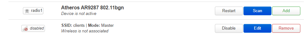
- This can be caused by the following
- You have upgraded your router and the pacakges are no compatible either the binaries or the sytax in the config files
- The relevant packages are not installed. Most likely you have upgraded your router, applied your config but not re-installed the required packages.
- In my case I think it was because I had enabled WPS via (hostpapd/wpad-wolfssd) but had not re-installed this and this setting in the config file was causing my 2.4Ghz wireless to fail.
- FS#2737 : Radio0 Device is not active - wireless configuration issue
- Archer C7 V5 - Wireless Device is not active - Installing and Using OpenWrt - OpenWrt Forum - could be a package issue
- This can be caused by the following
- VLAN
- You should really not uses these VLAN numbers
- 0 = untagged
- 1 = control plane so do use for networks
- You should really not uses these VLAN numbers